Update May 12, 2018
The complete kit is no longer offered since Sure Electronics discontinued the LED display.
I still sell the kit without the display, for those who can provide their own display, either from old stock or by making it themselves.
I may also have the bigger (5mm LED) display in stock, or may recycle some older ones. Please email me to inquire.
Update July 7, 2015
Before you buy, please read this post on assembling the Wise Clock 4 with the new display.
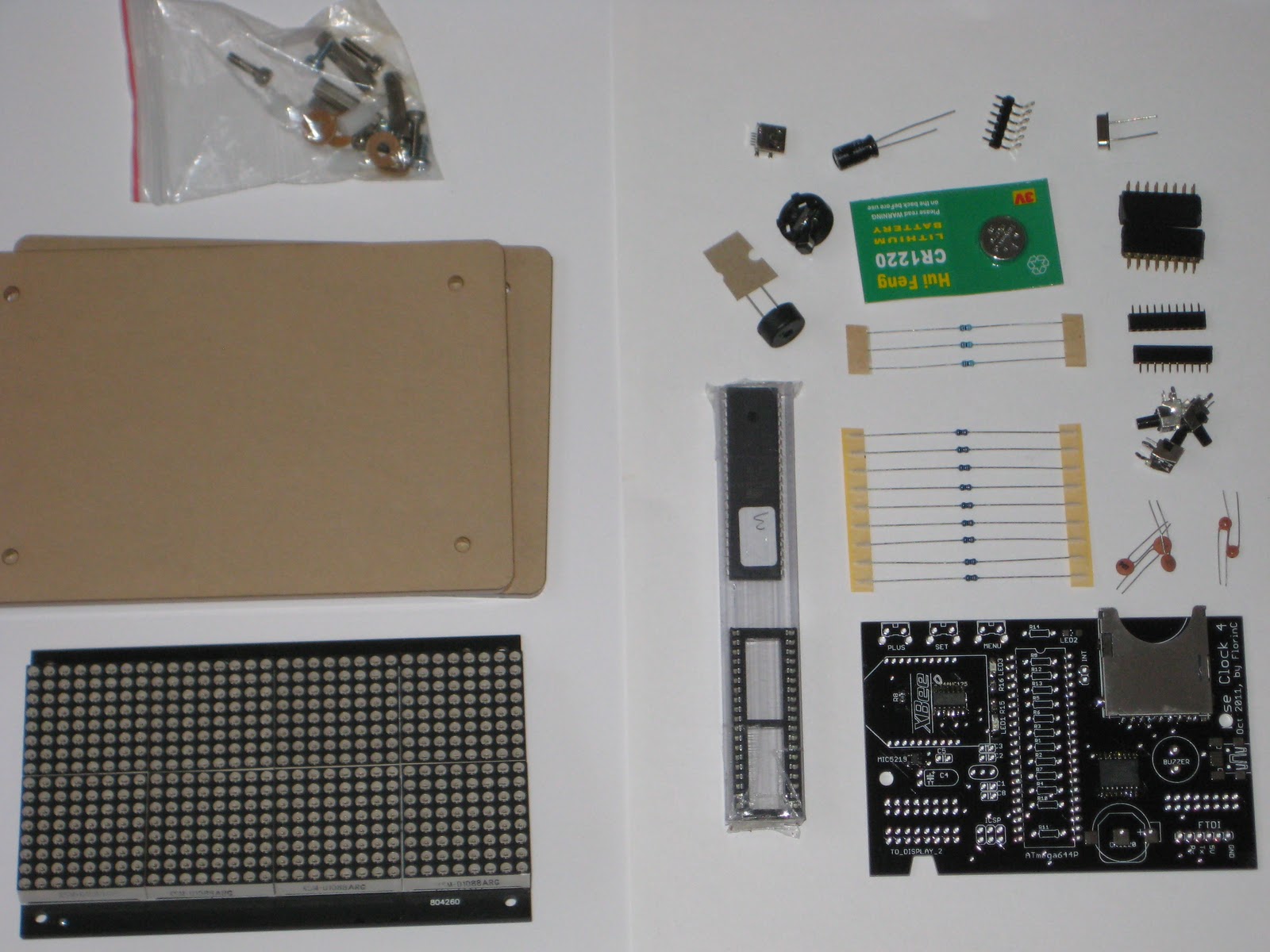
When you buy the "Complete Wise Clock 4 kit", on top of the Wise Clock 4 kit you get the 3216 bi-color (red/green/orange) LED display from Sure Electronics, plus the enclosure, consisting of two laser-cut transparent acrylic plates and the required hardware (standoffs, screws etc) to assemble it.
The assembly guide, written by StefanK, can be found here.


Automated Stitching of Chip Images
4 days ago
I just got by Wise Clock 4 and I thought I'd share since I've written a new clock for it. Probably boring for most of you though. This is an alarm clock for my toddler who can't tell time (of course). It uses colors to tell him when he should be sleeping and when he should get up.
ReplyDeleteI didn't need to, but I wrote all the code so its self contained including setting multiple alarms, setting the time, and turning the audio on and off.
http://www.youtube.com/watch?v=PFkEhJCB8zM
What are the differences between the Wise Clock 3 and 4? Why would someone want 4 over 3 or the other way around? Thanks.
DeleteVery Cool - do you have your code in a repo somewhere that we can play with?
DeleteChris,
DeletePlease take a look at this post:
http://timewitharduino.blogspot.ca/2012/04/guest-post-wise-clock-34-apr-2012.html
It also has a link to the source code. For some reason, google code says "deprecated", but it's not.
This is great! Definitely not boring.
ReplyDeleteShould be in its own (guest) post. Let me know if you want to write a short presentation of the features, eventually publish the code.
Hi Florin,
ReplyDeleteAs a Wise Clock 3 owner, I would like to know if it is possible to only buy the Wise Clock 4 board because I already own the rest of the hardware.
The board has all SMDs soldered on it, so it's not really "only the board". PM me and we'll work out the details.
Delete1. Are the LED driven in a dimmable fashion?
ReplyDelete2. Any code for getting the time via some wireless method?
Dwight,
Delete1. The LEDs are driven by LED driver chip HT1632. The display board itself, built by Sure Electronics, has 4 such chips.
Yes, the current software allows 5 levels of brightness for the display, user-selectable through a button.
2. Yes, either though GPS, as shown here (http://timewitharduino.blogspot.ca/2012/01/wise-clock-4-time-synchronization-with.html) or through WiFi (in the code already, but not explained in any post yet).
I hope this helps.
Is the lowest level of brightness set where it doesn't light up the room at night? I see that the board allows for 16 levels of brightness, so the the code should be tweakable fairly easy...
ReplyDeleteThe GPS option looks great!
The display allows for 16 levels of brightness, but the difference between adjacent levels are almost imperceptible, so I decided to have only 5 steps (every button push increases the level by 3). That can be modified, of course.
DeleteThe GPS option adds about $40 to the cost, with no obvious benefit, considering that the RTC in itself is extremely accurate (+/- 2 minutes per year).
At the dimmest level does it light up the room at night?
DeleteNot lighting up the room, but it can definitely be seen clearly. After all, these are LEDs :)
DeleteAnother question, does the clock auto-dim based an ambient light or time of day? Seems like that would be useful.
ReplyDeleteCurrently, the kit does not include a photo-resistor (nor a place holder for it) for automatic dimming. One customer added that though, see this post: http://timewitharduino.blogspot.ca/2012/08/status-update.html
DeleteWell, parts arrived, assembled and working :-) Many thanks.
ReplyDeleteHowever, I've not got the WiFi working yes, so I need to debug. Although I'm a software developer, I've not used Arduino before ... so I would like to check how things work. I presume I need to :-
1) Install the Arduino SDK ( arduino-1.0.6-macosx.zip )
2) Add in Sanguino ( sanguino_10+.zip )
3) Download source zip ( WiseClock_140705.zip ) and extract
4) Open TheClock.ino, select board Sanguino ATmega1284p and compile
In fact doing this I get "Binary sketch size: 71,408 bytes (of a 129,024 byte maximum)" which I think is a good sign.
5) Get a FTDI cable and connect to the clock
6) Upload the binary and use the serial port monitor for debugging
Is this about it ? Anything to watch out for ? I see there are 3.3V and 5V cables, which one do I need ? Is it okay to power the clock via USB and use the serial port at the same time ? Is this fairly safe ... ie I'm not going to brick it ?
But looking at the source I see WANT_WIFLY is disabled so that will be the first start :-)
Many thanks,
Pete
Pete,
ReplyDeleteYou got everything right (steps 1-6).
I use the 5V FTDI breakout to upload, debug and power the clock (from USB).
"Bricking" would mean disabling or overwriting the bootloader somehow. That never happened to me.
The easiest way to get WiFi for Wise Clock 4 is to use the WiFly module from Roving Networks ($35, Sparkfun). Then, you need to un-comment WANT_WIFLY, as you noted.
Similarly, you could use the newer and cheaper ESP8266, which also talks to the processor on serial (and also powered by 3V3).
I have a few posts on WiFly, search my blog for "wifly".
A
Well, I have a RN-XV module from Roving Networks and a serial cable.
ReplyDeleteAfter enabling debug, I found the code no-longer compiles. The fix appears to be to update AppUtc.cpp to :-
#ifdef _DEBUG_
Serial.print("Saved UTC difference: ");
Serial.println(wiseClock.utcDiff); // was just utcDiff
#endif
I see a log of junk data coming from the WiFly card such as :-
.4 xi
ei
M
<4
1ext
T
I'm not sure whats causing this ... but eventually the right response does come back buried in the junk and so the WiFi state machine progresses.
I also found a problem substituting $ for space for the wifi phrase ... looks like a cut & paste error ... the ssid is checked not the phrase. So the code should be :-
// replace any blanks in the phrase with '$' -- WiFly module converts it back
for (s = phrase; *s != 0; s++) { // was ssid
if (*s == ' ')
*s = '$';
}
doWep = false;
return;
With these two changes I get connected to the network and I can telnet to port 2000. However, the clock isn't being synced because of the apparent junk being returned over the serial port.
Any ideas what could be the cause of the just data coming back ?
Thanks,
Pete
Hi Pete,
DeleteThanks for the bug fixes.
I haven't touched the WiFly code in a long while now and I don't remember much.
I will take a look in the following days, I hope.
But you seem to be better at finding solutions to this :)
Keep up the great work!
Happy New Year!
I looked (visually) at the WiFly code (which I did not write).
DeleteIt seems to require a NTP server IP address (in message.txt file). First check is to make sure that the NTP is valid and active.
I have a "Time" library downloaded from some place (not sure where), that has a TimeNTP.pde sample sketch. It enumerates these NTP servers:
byte SNTP_server_IP[] = { 192, 43, 244, 18}; // time.nist.gov
//byte SNTP_server_IP[] = { 130,149,17,21}; // ntps1-0.cs.tu-berlin.de
//byte SNTP_server_IP[] = { 192,53,103,108}; // ptbtime1.ptb.de
So, I would think that first we need to make sure we get correct data from an active NTP server. Maybe it is easier to perform the test with the sample TimeNTP sketch.
(I also realized that I lent my WiFly to a friend.)
I think the issue I'm seeing is the serial link between the ATmega and the RN-XV ... I've tried various software uart settings, but I'm now wondering if there is a hardware issue.
ReplyDeleteI think that being able to connect to WiFi network (passing ssid, password etc) proves that the serial communication on the second UART works.
DeleteWhat exactly is not working? Do you get runtime errors/ timeouts?
It looks like sending data to the Wifly works but receiving data is garbled.
DeleteCould it be the WiFly module itself?
DeleteYou could try a simple sketch that only sends and receives.
Also, keep in mind that any response longer than 2K is truncated/lost, since the WiFly's RAM buffer is only 2K.
Thanks for the tip - a separate sketch works fine - data from the the WiFly is not corrupted.
ReplyDeleteBut, I think I see the issue. WiseClock::checkSerial() is reading from the WiFly ( to get any messages to display ) at the same time as CWiFly::check() is also reading. So CWiFly::check is only getting around 1/2 the characters. If I simply comment out the reading of Serial1 in WiseClock::checkSerial() then I see un-corrupted responses from the WiFly in command mode.
I'll see if there is a way to better synchronise these two readers tomorrow. But also, there is a conflict if USE_SOFTWARE_SERIAL is set ( WiseClock.cpp uses this but WiFly.cpp doesn't ).
BTW - is a source repository available somewhere (read only ) ? It might be easier to email you diffs against the latest.
Many thanks for your time,
Pete
From what I remember, USE_SOFTWARE_SERIAL was defined for the JY-MCU Bluetooth module that connects to 2 digital pins and uses SoftwareSerial library. It should not interfere with the use of UART2 (second hardware serial port).
DeleteI don't have a github repository yet, but I will create one soon, I hope.
But if you send me the modified files, I could merge the changes into my code (I also have other changes from the code you are working on).
I really appreciate your help and your contribution. At this point of complexity, I think it takes a great mind to understand how things work and to be able to fix bugs.
DeleteI thank you!
This appears to work ...
ReplyDeleteIn WiFly.h, add in public flag :-
boolean cmdMode; // using command mode
In WiFly.cpp, initial the flag to false in CWiFly::configInit() :-
cmdMode = false;
In CWiFly::check(), only read from serial if cmdMode is true :-
if (wiFly.cmdMode == true) {
while(Serial1.available() > 0) {
....
}
}
if (timerActive) {
....
Set cmdMode to false on receipt of EXIT :-
if (confMatch(msgBuf, PSTR("EXIT"), 4, 0, 0)) {
if (msgBuf[4] == 0) {
cmdActive = false;
cmdMode = false;
}
set cmdMode to true before entering command mode :-
case WIFLY_CMD_START: // switch to command mode
cmdMode = true;
print_P(PSTR("$$$"));
In WiseClock.cpp, only read from serial1 if commandMode is false :-
void WiseClock::checkSerial()
{
#ifdef SERIAL_MSG
char c;
#ifdef _WiFly_H_
if (wiFly.cmdMode == false) {
#endif
.....
#ifdef _WiFly_H_
}
#endif
#ifdef _WiFly_H_
wiFly.check();
#endif
With this I can get both the WiFi settings okay ( with no garbled responses ) and can set the message by telneting to port 2000.
Feels like it needs a android app to manage the clock :-)
Thanks,
Pete
I'm not convinced this is the best way ... in my tree I've now done it the other way around - ie disable reading of the messages over wifi in WiseClock.cpp and keep it in WiFly.cpp.
DeleteOne annoyance is the bright LED's on the WiFi board ... however these can be disabled. Maybe in WiFly.cpp :-
ReplyDeletecase WIFLY_SET_PRINTLVL:
print_P(PSTR("set sys printlvl 0\r")); // disable verbose messages
#ifdef WiFly_DBG
print_P(PSTR("set sys mask 0x2100 1\r")); // disable LED's
#endif
Good stuff, thanks.
DeleteA cheaper alternative to WiFly is ESP8266 (less than $5), but the code is a little different, I think.
An alternative I have been contemplating is something I named "WiseDock", a RPi device (with WiFi) that streams out the results of processing http responses on BT. Since Wise Clock is already able to display messages from BT, no code changes would be required.
Thanks :-)
DeleteI wanted to read the date as well as the time from WiFly module ... however this appears to have a bug.
ReplyDeleteRunning "show t t" you get the time as well as the UNIX timestamp - although the time is shown with a timezone offset.
A good example is :-
show t t
Time=14:57:20
UpTime=14267 s
RTC=1420322240
The timestamp 1420322240 is Sat, 03 Jan 2015 21:57:20 GMT.
However I sometimes see something like :-
show t t
Time=13:28:16
UpTime=8528 s
RTC=1420316996
1420316996 is Sat, 03 Jan 2015 20:29:56 GMT ... so 100 seconds out.
I've reported this to microchip.
Here is my clock.
ReplyDeleteI use the microcontroller atmega1284p. I added a MIDI board to play simple melodies. I also installed the WiFly module to adjust the current time and display forecasts.
http://hobby.farit.ru/arduino-clock-atmega1284p-midi-internet/
Very nice!
DeleteThanks for sharing.
This comment has been removed by the author.
ReplyDeleteHi !
ReplyDeleteIs there an alarm in default code ?
A combination between the pong and the following clock will be great for me :
http://www.youtube.com/watch?v=PFkEhJCB8zM
Where is the code ?
Do you provide source code I can play with ?
BR
Yes, there is alarm.
DeleteThe mod in the video was introduced here (with a link to the source code provided):
http://timewitharduino.blogspot.ca/2012/01/zeeclock-nice-mod-running-on-wise-clock.html
The latest published software release is here:
http://timewitharduino.blogspot.ca/2014/07/july-2014-release-of-wise-clock-4.html
Thanks for prompt reply, kit ordered :-)
DeleteI can't wait to play with this clock.
BR
Hi !
ReplyDeleteSoldered everything, but sadly one led panel is malfunctioning, green leds of one column are dead.
What to do ?
Checks to perform or return it to you for exchange ?
Best regards
Yves,
DeleteDisappointing to hear that.
Return (to replace) would be fine. But let's try fixing the display first. I'm sure it's just a cold solder joint (it happened to me before). Could you try re-soldering the pins of the LED matrix with the malfunctioning LED?
Tried but not working.
ReplyDeleteBut, I god it working by pressing hard both boards together.
The issue must be due to a connector.
Please send me another display board and black 2x8 connector (I'll pay both).
Then if it works I send you back the defective display.
Best regards
Yves
It's confirmed that it's the display board that is creating the issue.
ReplyDeleteI changed the connector on main board, no difference.
I then installed pin wires between boards, same issue.
Only when I press hard on display board the green is working again.
I return the display board to you, please send me quickly a new one.
Best regards
Again, it sounds like a cold solder joint somewhere on the display board. Before you return it, please try re-soldering ALL parts related to the LED matrix with the problem: the matrix pins (24 pins), the SMD current-limiting resistors (8 resistors, 16 pads) and the HT1632 pads.
DeleteThis comment has been removed by the author.
ReplyDeleteHi,
ReplyDeleteJust received the replacement display, it's working perfect now, THANKS !
Is there a manual somewhere for the settings ?
And posts that explain the XBee and BT options ?
Best regards
Yves,
DeleteA brief user manual can be found here:
http://timewitharduino.blogspot.ca/2011/08/wise-clock-3-user-manual.html
Regarding the JY-MCU bluetooth module I sent you, this post (first photo) shows how to install it. That BT module requires software serial option to be enabled in the code.
(I upload that code on some of the processor, I don't remember what yours is, but you can always upgrade).
As for the XBee module I sent you, I did not use it with Wise Clock (I long while ago, I have some unsuccessful tries to connect to an XBee internet gateway and I gave up.). Should be pretty straightforward for you to use it, lots of examples on the interwebs. The hardware support (3V3 power, level shifting) is already there.
DeleteI have a board labelled WiseClock4+ Aug 2012.
ReplyDeleteThe kit came with two 100nF capacitors. The board has four places to put them. Am I missing pieces? If not, which of the four spots gets the two caps? Also there are two spots for 22pF caps but none came in the kit.
Emma/Andy,
DeleteThe kit normally includes 3 capacitors of 100nF.
If you only have 2 (and cannot get a third one), then solder the 2 closest to the 22pF capacitors. They are named C3 and C8 in the silkscreen.
C3 is used for decoupling on the processor power line, C8 is used for the reset when you upload a sketch, C5/C6 are decoupling on the 3V3 line (which already has a 470uF).
I hope this helps.
FlorinC