Thursday, February 24, 2011

Uploading sketches to Wise Clock 3/4

Update Apr 29, 2015
Here is another great tutorial on how to install the sanguino files, brought to you by the evilmadscientist team, the creators of Alpha Clock 5, another sanguino-compatible device.
It also seems that sanguino.cc was "upcycled" into something more revenue-producing.

Updated April 7, 2013 - added details (sanguino section in boards.txt etc).
Although this post was written for Arduino 21, it applies almost identically to Arduino 1.0 and later.
I say "almost" because:
  • file WProgram.h was replaced by Arduino.h
  • the original sanguino files may not be maintained publicly anymore. Instead of copying them from sanguino.cc, as suggested originally, you can download my updated (for Arduino 1.0+) version from here.
-------------------------------

Sooner or later, if you have Wise Clock 3 or 4, you may want to upgrade the software.
This process requires the following prerequisites:
  1. the Sanguino-related files need to be installed (since Wise Clock 3/4 is compatible with Sanguino);
  2. an FTDI cable/breakout is required to upload the sketch to the board.

To install the Sanguino files, you may follow the instructions found here. Basically, you need to do two things:
  • Firstly, add the definition of the Sanguino board to the file arduino21/hardware/arduino/boards.txt;
This "Sanguino" section should look like this:

sanguino.name=Sanguino
sanguino.upload.protocol=stk500
sanguino.upload.maximum_size=63488
sanguino.upload.speed=38400
sanguino.bootloader.low_fuses=0xFF
sanguino.bootloader.high_fuses=0xDC
sanguino.bootloader.extended_fuses=0xFD
sanguino.bootloader.path=atmega644p
sanguino.bootloader.file=ATmegaBOOT_644P.hex
sanguino.bootloader.unlock_bits=0x3F
sanguino.bootloader.lock_bits=0x0F
sanguino.build.mcu=atmega644p
sanguino.build.f_cpu=16000000L
sanguino.build.core=sanguino
sanguino.verbose=false

Pay attention to the upload speed (38400), which is "burned" in the bootloader and essentially important for communication with the board (sketch upload, serial monitoring). Also pay attention to the second last value, which indicates the folder where core files are found. This parameter MUST not be "arduino", but "sanguino". Thanks to Dave, who found this potential issue. Even though compilation and uploading were successful, the sketch failed to run as expected. This was because the core files used at build time were not those  for ATmega644/ATmega1284 (as used in sanguino).

If your processor is ATmega1284, the "Sanguino" section in boards.txt should look like this:

atmega1284.name=Sanguino W/ ATmega1284p 16mhz
atmega1284.upload.protocol=stk500v1
atmega1284.upload.maximum_size=129024
atmega1284.upload.speed=57600
atmega1284.bootloader.low_fuses=0xFF
atmega1284.bootloader.high_fuses=0x98
atmega1284.bootloader.extended_fuses=0xFD
atmega1284.bootloader.path=atmega
atmega1284.bootloader.file=atmega1284p_16MHz.hex
atmega1284.bootloader.unlock_bits=0x3F
atmega1284.bootloader.lock_bits=0x0F
atmega1284.build.mcu=atmega1284p
atmega1284.build.f_cpu=16000000L
atmega1284.build.core=sanguino

Note that for ATmega1284 the upload speed is 57600. Also note that the core folder (last parameter in the list above) is still "sanguino".

  • Secondly, create the folder "sanguino" and copy the Sanguino files, as shown in the screenshot below.


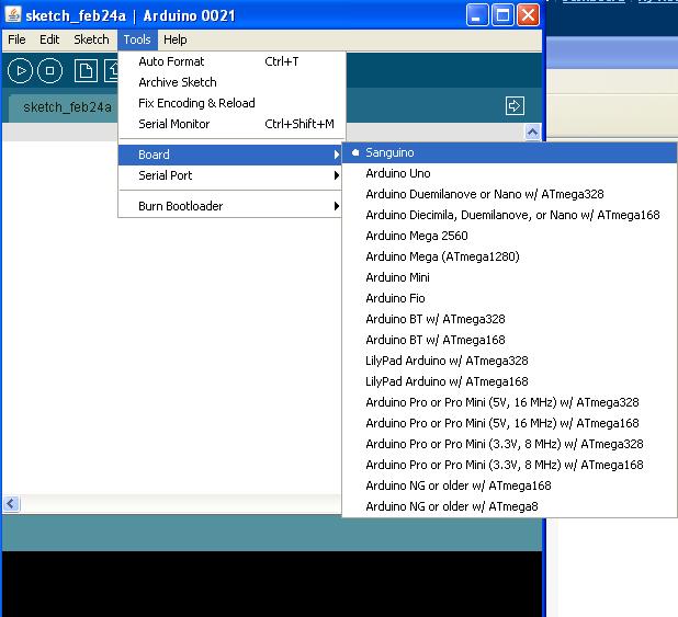
After these two steps are completed, you should see "Sanguino" listed in the menu "Tools/Board" of Arduino IDE 21 (used as an example here).


To upload the sketch, you will need to connect the board to the PC/Mac with an FTDI cable/breakout. The USB end of this cable gets plugged into the PC/Mac, the FTDI end gets connected to the Wise Clock 3/4 board as shown in the photo below.


With both the software and hardware in place, the upgrade will consist in the following steps:
  • download the latest software on the PC;
  • launch Arduino IDE and load the sketch;
  • compile, after chosing "Sanguino" as the target board;
  • upload to the Wise Clock 3/4 board.
Unziping the WiseClock3/4 source code (found here) should result in a directory structure as shown in the screenshot below.


If you get compilation errors related to "tone.cpp" file, like the following,

...\ArduinoIDE\libraries\WiseClock3\Sound.cpp: In function 'void soundAlarm()':
...\ArduinoIDE\libraries\WiseClock3\Sound.cpp:60: error: 'tone' was not declared in this scope
...\ArduinoIDE\libraries\WiseClock3\Sound.cpp: In function 'void beep()':
...\ArduinoIDE\libraries\WiseClock3\Sound.cpp:75: error: 'tone' was not declared in this scope

make sure the file Tone.cpp is present in the sanguino folder, as shown in the next screenshot.


(April 7, 2013: The following info is obsolete now. File WProgram.h was replaced by Arduino.h.)

Also, make sure that WProgram.h (in the sanguino folder) contains the line

void tone(uint8_t _pin, unsigned int frequency, unsigned long duration = 0);


Sunday, February 20, 2011

FM Radio + MP3 Player Module

Updated Oct 30, 2011
Not a failure anymore! Thanks to Viraj's advice, by connecting the audio ground to GND, the USB works fine as well.
I also found this rather brief instructable, which shows how to connect the buttons, basically shorting V+, V-, Mode and P to the ground.
The module takes around 53mA when playing the radio, and about 90mA when playing from USB stick (medium volume and using headphones). The current would be lower with the LED display turned off (I guess that display itself takes at least 20mA). So a small-sized LiPo battery of 300-500mAh could last a few good hours.

Now that it's all kind-of figured out, this small module could be integrated into a larger project, eventually controlled by Arduino; radio alarm clock comes to mind. (I wish the module had integrated RTC and work as clock as well.)

These modules, manufactured by Vire, seem to be used in a lot of devices. They also come in various formats and shapes, with different displays (LCD, for example). They can be bought from alibaba.com in bulk for about $5.
There are also variations of the small Vire module, probably made by other manufacturers, that include the extras (SD card socket, infrared receiver, USB socket, buttons). These, like the one pictured below (from dealextreme), retail for under $15.


On the other hand, they can be bought as finished consumer products (encased, even including the LiPo battery and charger, cables, speaker) for about $15 (ebay, dealextreme, amazon).


----------------------------------------------

This is a posting about failure. I wanted to document it before I shelve it and forget about it.

A while back I bought an "FM radio and MP3 player" module, with the purpose of integrating it with an Arduino. (I looked into many other FM radio modules, but this seemed the lowest cost and easiest to interface.) Here it is in the photo below.


The FM radio module I received was capable of much more than just digital radio receiving, it seemed:
  • show, on a 3 1/2 7-segment LED display, the FM radio station frequency (MHz);
  • scan FM range and memorize up to 30 stations;
  • control from an infrared receiver, with the provided (included) remote control;
  • play MP3 files from USB memory stick or SD card;
  • interpret and execute complex commands: volume up/down, mute, repeat, equalizer (5 types, preset).

The module is designed to interface with the peripherals through JST 1mm-pitch connectors. Unfortunately, the connectors and cables were not provided. (I recycled some from a junk CD player).
With no application note/schematic/datasheet, the only way to connect it was to resort on the names of the pins found on the silkscreen.
The bottom connector has the following pins:
L, G, R, V+, MODE, V, P, G, IR, 3V3

I correctly assumed that L is "Left audio channel", "G" is ground, "R" is right audio channel, "IR" is infrared input from an external infrared receiver.
I assumed incorrectly that "P" is positive (Vcc), because pins P-G-IR coincide with the terminals of the infrared receiver.
Once powered (5V), the radio, which is the default mode, starts working and an FM frequency is shown on the display. The only way to control the module at this point was through the remote control. After re-connecting the Vcc of the infrared receiver from pin "P" to "5V", the remote control started to work.


So far so good. Now, on to the MP3 player and USB.
I managed to get the schematic for the module


which showed how to wire the 4 pins of an USB type-A connector: GND, DP, DM, 5V. These are the 4 bottom pins of the lateral 10-pin connector.

With the USB memory stick (with a few MP3 tracks on it) inserted, the module seems to be reading it: the LED on the USB stick flickers. But, and this is where the failure is, there is no sound in the headphones, as it is when the radio is active.

While struggling with this module, I found a radio+MP3 player device that I believe uses internally a similar one. The major difference seems to be the display, which is LCD instead of LED.


I tested the USB memory stick with it and it plays just perfect.
I tried to open it up to look at its internals, but it seems to be glued together with no chance to put it back once opened. The case is made of pressed particle board, covered in some plastic veneer. There are just 4 screws in the back, which I was able to remove for a peek inside.


The box is mostly empty, except for the 2 side speakers and a rechargeable battery glued to the top (green object in the photo above). The small board shown is the audio amplifier. The FM+MP3 module is in the front of the enclosure, I guess, together with the LCD display and the sockets for USB type-A and SD card,


So here is what I have so far:
  • Both modules I have behave the same (USB mode is "silent", no sound from the USB memory stick), although the USB stick seems to be read correctly, based on the flickering LED.
  • The audio part works fine, since the radio is audible.
  • I double checked my connections, the 4 wires from the module to the USB connector (proof is that the USB seems to be read, as well).
  • I made sure the MP3 files are accessible and playable by a similar device.
I ran out of ideas. Looking at the schematics, I realize that it could be also a software (microcontroller) bug. The audio signal is output by the microcontroller through pins 14 (DAC_L) and 16 (DAC_R), I assume.
Since the radio works (using the same pins), I also assume that these pins are correctly connected to the audio amplifier.

Tuesday, February 8, 2011

Assembling Wise Clock 3/4 kit

Updated Dec 16, 2012
StefanK from Germany put together this a nice assembly guide for Wise Clock 4. Thanks Stefan!

Updated March 25, 2012
Here is a troubleshooting guide.

Updated March 10, 2012
Follow these same instructions to assemble Wise Clock 4 as well.
There are a few minor differences:
  • the optional power LED and resistor (both SMD) are not included; so skip step 2;
  • there are 2 extra resistors (R17 and R18), both 10k, on the right side of the processor;
  • the 470uF electrolytic capacitor (C4) must be placed with the minus terminal (marked with a band) towards the bottom of the board (this capacitor is useful only if an XBee/WiFi radio module is present);
  • the reset button is not used anymore;
  • the voltage regulator (78L33, through hole) was replaced with MIC5219 SMD, which is already soldered on the board.


Updated May 16, 2011
Thanks Scott for contributing this PDF version of the assembling instructions.

The Wise Clock 3 PCB comes with the SD card socket and the RTC chip already soldered, and looking like this.


Follow these steps:

1. Place and solder the miniB USB connector; actually, since this connector is only used for power, only the two extreme pins (1 and 5) must be soldered; the middle three can be left untouched. Make sure the connector is solidly anchored to the board through the 4 lateral holding pads; there will be lots of mechanical tension when the power cable is plugged/unplugged.


2. Solder the 100 ohm resistor (brown black brown), indicated on the PCB as R14, then the LED, paying attention to its orientation. The shorter pin, the cathode, goes into the left (as you look at the PCB as in the image below) hole. At this point, by plugging in the power cable, the LED should light up.


3. Solder resistors R5, R6, and R7, all 4K7 (yellow purple black brown brown), as shown in the next photo.


4. Solder the rest of the resistors, all 10K, as shown in the photo below.

Note that there are 9 resistors of 10K value (brown black orange): R1, R2, R3, R4, R9, R10, R11, R12, R13.


5. Solder the 40-pin socket, then the battery holder and the 4 buttons, see photo below.


6. Solder the 3 decoupling capacitors (100nF, labeled "104"): C3, C5, C8. Then continue with soldering the two smaller ones C1, C2 (both 22pF).


7. Insert the crystal (the small, metallic, oval cylinder, with 2 pins, labelled "16.000" on its top) in its position on the left side of the microcontroller socket, indicated by an oval (see the above image). Orientation is not important for the crystal.
Then insert the 3V3 voltage regulator (black, 3-pinned, semi-cylindric part labeled "L78L33ACZ") as indicated on the silkscreen by the half-cylinder on the right side of the microcontroller socket (its orientation is very important), then solder in place.
Next solder the 6-pin male header, and then the piezoelectric buzzer (its orientation is not important).
Look at the photo of the final assembled board (two photos down) before soldering, to make sure you have these parts placed correctly.

8. Insert the two 16-pin female headers on the back of the board (opposite to the parts side) and solder them on the top (parts) side.

To get the best alignment possible on these headers, Justin (thanks) suggested to insert the 16-pin headers into their sockets (in the display), then solder the board on top. (This is similar to the way the male headers are soldered on an Arduino-shield.)


9. It is time to add now the preprogrammed ATmega644P microcontroller. Before inserting it in the socket, slightly bend both sets of its pins on a table, so that they become parallel. Position the chip carefully on top of the socket, paying attention to its orientation: pin 1, marked with an arrow (triangle), must be close to the upper side of the board. Push the chip firmly into the socket.
Next insert the coin battery in the battery holder.
The assembled board should look like in the photo below.


10. Plug the Wise Clock 3 board into the 3216 LED display from Sure Electronics (not supplied in the Wise Clock 3 kit).


11. Copy the files (provided in the zip) onto the SD card, formatted FAT16, then insert the SD card in the socket.

12. Power the board with a miniB USB cable. You made it! Congratulations! Next, set up the clock (date and time) from the buttons. Then chose your favorite clock mode and enjoy.


Related posts:

Saturday, February 5, 2011

Wise Clock 3 kit now available in store

Updated Oct 21, 2011
This "Wise Clock 3 kit" does not include the display. To build the clock, you need to provide your own 3mm 3216 display (about $30 on ebay) and make your own enclosure.
"Wise Clock 3 complete kit", which includes the 3mm display and the laser-cut enclosure, is offered for sale here.

Now that I have a version of the software working well with Wise Clock 3 board, I can offer a "Wise Clock 3 kit" for sale. This board is designed to plug directly into the 3mm 3216 LED display from Sure Electronics. The software is pre-loaded onto the microcontroller chip.

Note: Wise Clock 3 board can be connected to the 5mm 3216 display only through the ribbon cable that comes with the display. If you insist on using the 5mm display (which I do not recommend), you will need to replace the right (looking at the top/component side) connector with your own 2x8 male header.


  (US$62, free shipping to North America)


This is, in summary, what Wise Clock 3 can do (Edit: the software is upgraded periodically, here is the latest):
  • display the current time, retrieved from the highly accurate real time clock that is DS3231;
  • along with the time, display quotations retrieved from a user-editable file on SD card;
  • display a personalized, user-editable, message, e.g. "Happy birthday John", "Happy Valentine's Day my dear love";
  • display the date and temperature;
  • display the time as a Pong Clock;
  • sound alarm at the specified, user-settable (through buttons), time;
  • set the time, date and day of week from buttons;
  • enable/disable the display of personalized message, date, temperature.


The content of the Wise Clock 3 kit is shown in the above photo and includes the following parts:
  • PCB;
  • ATmega644P microcontroller with the Arduino bootloader, preprogrammed with the latest Wise Clock 3 software;
  • 40-pin socket for the microcontroller;
  • SD card socket (*);
  • DS3231 real-time clock (*);
  • 16MHz crystal;
  • CR1220 coin backup battery for RTC;
  • holder for the coin battery;
  • piezoelectric buzzer;
  • miniB USB connector;
  • 9 x 10K resistor;
  • 3 x 4K7 resistor;
  • 100 ohm resistor;
  • blue LED;
  • 4 right-angle micro push buttons;
  • 2 x 16-pin female headers (display connectors);
  • 6-pin right angle male header (FTDI connector);
  • 3V3 voltage regulator;
  • 3 x 100nF decoupling capacitors;
  • 2 x 22pF capacitors.
(*) I solder the SD card socket and DS3231 chip for you.


   (US$62, free shipping to North America)

Tuesday, February 1, 2011

Naming conventions

This is becoming a bit confusing even for myself. I could not find a name for the board powering the "Wise Clock 3", so I just named it "Wise Clock 3" board. On the other hand, the board that powers "Wise Clock 2" is Duino644. It sounds a bit silly, I know. I am still debating on the name for the new board and I am also open to suggestions. Until I find a better name, here is some help to clear the confusion.


"Wise Clock 3" is pictured on the left. It has a wider display (32x16, bi-color). The green board, as I mentioned, is called (for now) "Wise Clock 3 board".

"Wise Clock 2" is on the right side of the photo. It has a 24x16 single-color (either red or green) display. It is powered by the black board, named "Duino644".

Both Wise Clock 2 and Wise Clock 3 have similar functionality, but the latter has more features allowed by the bigger and better display. In the photo below they are working side by side.


Related posts: